Transfer Optics and Calibration Assembly
The Transfer Optics and Calibration Assembly (TOCA) encompasses three subassemblies, namely the ASM Calibration Assembly, the Polarimetric Calibration and Alignment Assembly, and the M3-M6 Mirror Assembly.
ASM Calibration Assembly
This assembly is needed to generate the interaction matrix of the Adaptive Secondary Mirror (ASM) using the red wavefront sensor and an artificial light source at F1.
Polarimetric Calibration and Alignment (PCA) Assembly
The PCA Assembly is positioned near the F2 focal plane, as shown in Figure 1. This location allows for the calibration of the maximum number of optical components along the optical path and avoids working with large apertures thanks to the beam size at this position.
The PCA assembly performs multiple functions. It is used to accurately determine the Mueller matrix of the telescope (which makes the precise determination of the polarisation state of the incoming solar light feasible) and to calibrate both the ASM and M7, the deformable mirror in the POP. The PCA assembly also allows to align the optical elements down to the instruments and to verify the telescope optical quality. Finally, it houses the field stop for observations, enabling a circular field of view of 127 arcsec at F2. The proposed configuration consists of four levels:
- Level 3, housing an illumination unit and the ASM calibration unit to determine the M2 figure error.
- Level 2, where the linear polarizer(s) required for the polarimetric calibration of the telescope will be placed.
- Level 1, housing the calibration retarders needed for the polarimetric calibration of the telescope.
- Level 0, is the alignment unit and accommodates the necessary elements for verifying the telescope’s alignment and optical quality such as pinholes, reticules and so on.
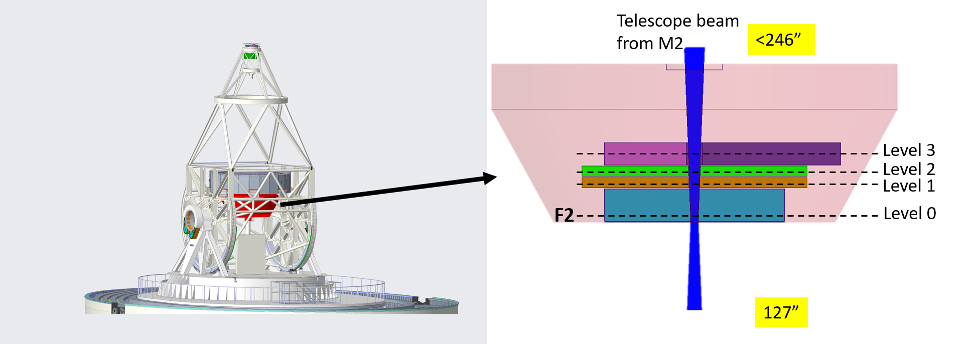 Figure 1. Location of the PCA Assembly. The inset indicates the space reserved for each subsystem that comprises the PCA Assembly.
M3-M6 Mirror Assembly
These four folding mirrors work in pairs such that both elements of each pair are tilted by 45 degrees in perpendicular incidence-reflection planes to self compensate the instrumental polarisation they generate, provided their reflection coatings have the same properties and no dust is deposited over the surfaces.These mirrors also generate the elevation (M4 and M5) and azimuth axes (M6), as depicted in Figure 2.
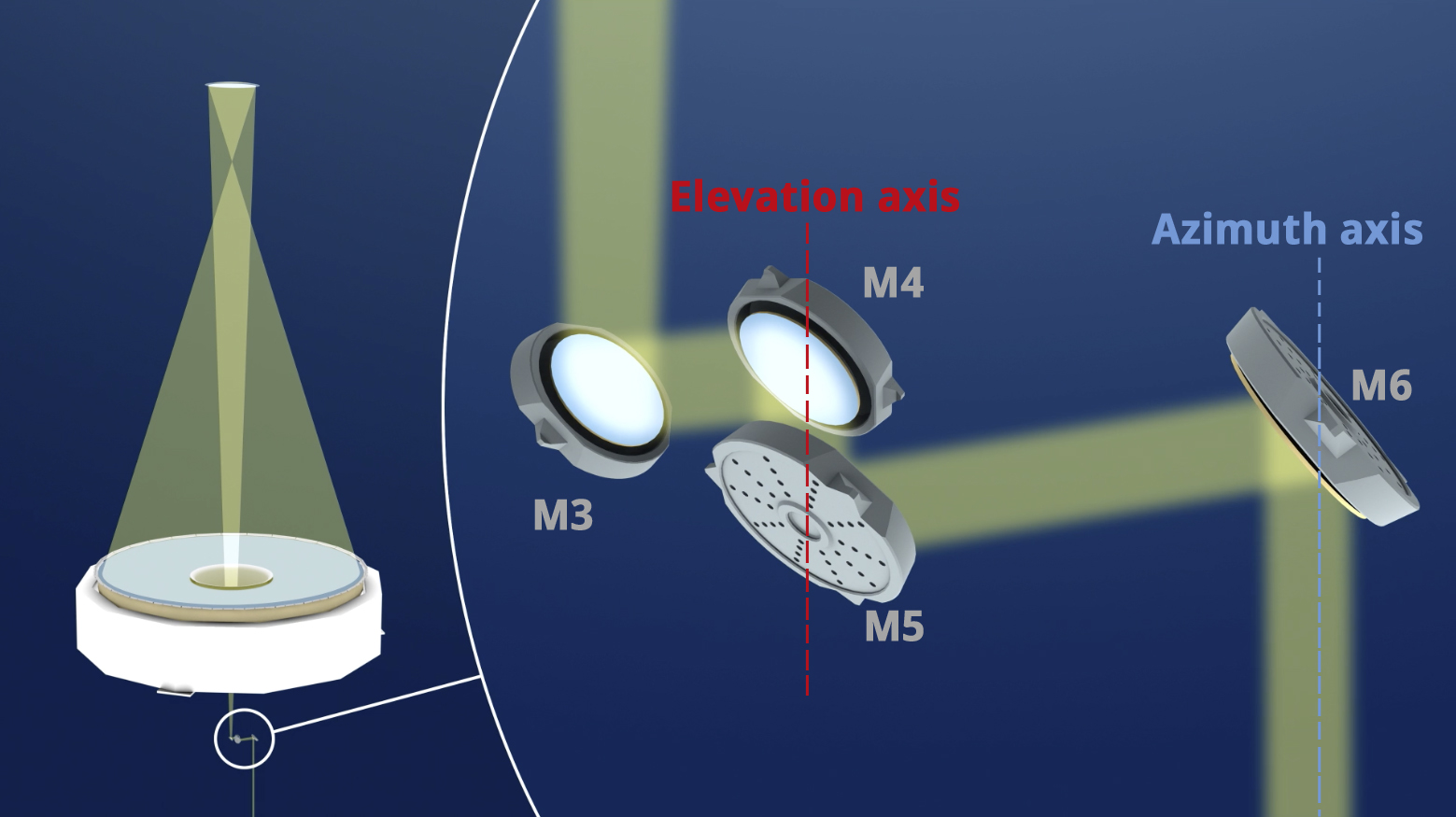 Figure 2. M3 - M6 arranged in incidence-reflection planes perpendicular to each other, generating the elevation and azimuth axes.